Lattice design (caDNAno)
1. Crossovers between neighboring helices
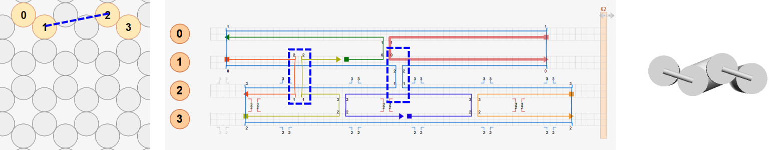
When analyzing a lattice design stored in caDNAno format, CanDo assumes that all crossovers between neighboring helices in the design are located at their natural positions defined in the caDNAno at which torsional mismatch between neighboring helices is minimal. These natural crossover positions can be seen in the caDNAno design panel when a strand is clicked as shown in the figure below.

Currently, users must follow this crossover rule to design DNA origami structures for CanDo analysis. Below is an example two-helix bundle design that follows the crossover rule whose 3D solution shape is expected to be straight.

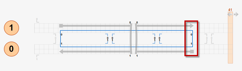
If a design does not follow the crossover rule, unexpected results may be obtained from the CanDo analysis. For example, in the modified two-helix design below, the right scaffold crossover is enforced at the position that is three basepairs left from its natural position as highlighted in the red box. Although there is torsional mismatch between basepairs connected by this crossover, expected to result in left-handed twist, CanDo predicts the straight solution shape because all crossovers are treated as natural ones.
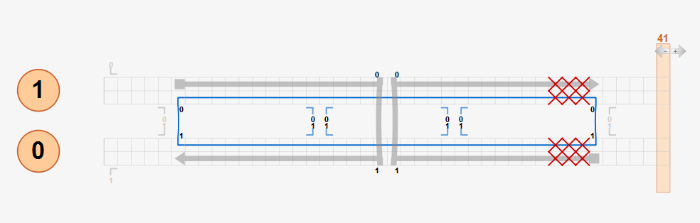
To simulate the effect of this mismatch properly, the design should be modified using insertions or deletions with natural crossovers as below. Three deletions at each helix are added to the design while using natural crossovers only. CanDo predicts left-handed twist on the right half of the bundle correctly as expected.
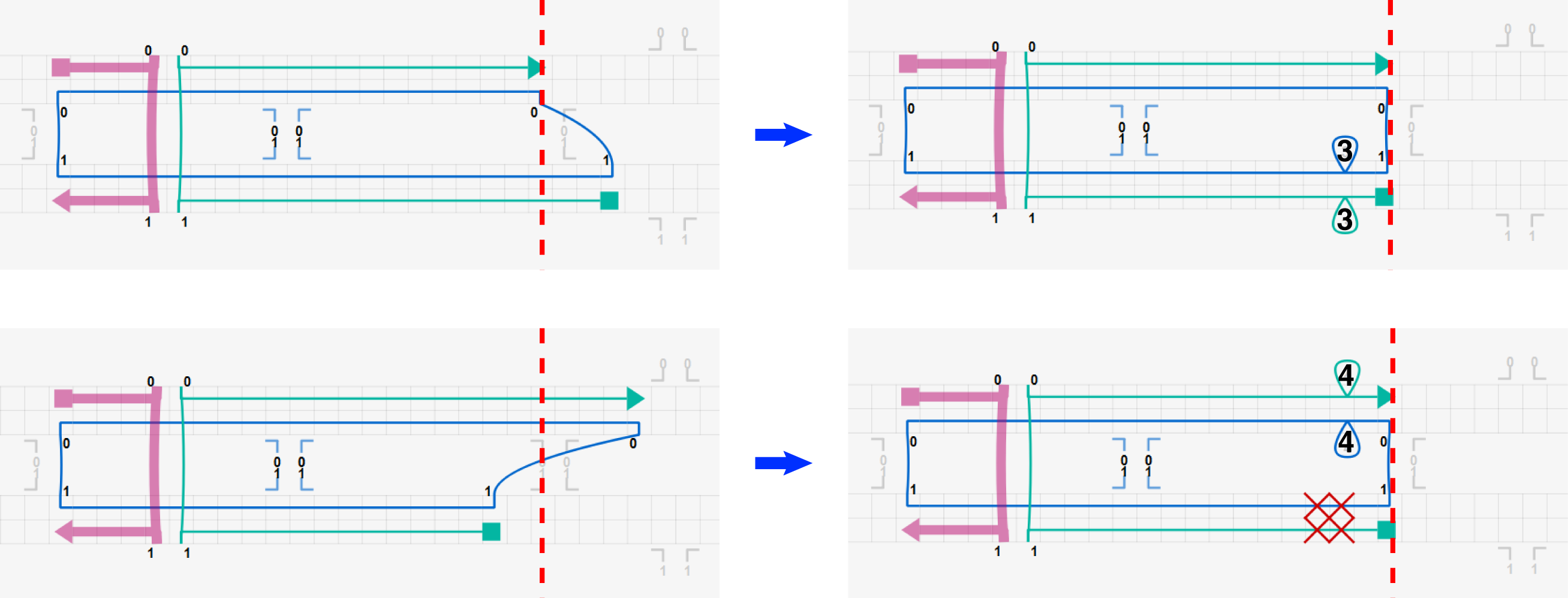
Two more example design modifications are shown in the figure below where red dashed lines indicate natural crossover positions.
The algorithm used in II. Lattice-free design (Tiamat or .cndo) is able to account for the mismatch due to unnatural crossovers.
2. Crossovers between non-neighboring helices
In wireframe structure design, crossovers between non-neighboring helices are used to connect substructures that are initially distant to each other but should be adjacent in the final relaxed configuration. When analyzing a lattice design, CanDo defines these crossovers as distant crossovers that gradually shrink during the analysis until their length reduces to the distance between neighboring helices or the helix diameter. However, relative orientations of helices connected by distant crossovers remain unconstrained so that CanDo analysis is limited at present to on-lattice modeling of DNA origami structures. Thus, careful use of distance crossovers is advisable.
To illustrate this, let’s consider three test designs of four-helix bundle that have the same connectivity map. The first design consists of four neighboring helices with crossovers at the natural positions. Because all basepairs are aligned at crossovers, the deformed shape (right) is the same as the initial layout (left).
In the second design, the entire structure is divided into two sub-bundles (helices 0-1 and helices 2-3) separated vertically in the initial layout. Two sub-bundles are connected by distant crossovers between helix 1 and helix 2 at the same axial positions used in the first design so that basepairs connected by these distant crossovers are already torsionally aligned (highlighted with blue dashed lines). Hence the same deformed shape is obtained as in the first design.

In the last design, helices 2-3 are placed in an arbitrary position. Basepairs connected by distant crossovers between helix 1 and helix 2 are not torsionally aligned. In addition, all crossovers between helix 2 and helix 3 violate the natural crossover rule. In this case, the deformed shape predicted by CanDo will be different from that of the first and second designs.
The computational model used in II. Lattice-free design (Tiamat or .cndo) allows for more general crossovers, enabling lattice-free DNA origami design.
Lattice-free design (Tiamat or .cndo)
1. Two isomeric states of a four-way junction
When analyzing a lattice-free design stored in Tiamat or .cndo format, CanDo assumes that each four-way junction exhibits a stacked-X conformation that has two possible isomeric states as shown in the figure below.
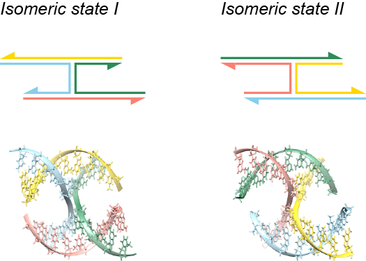
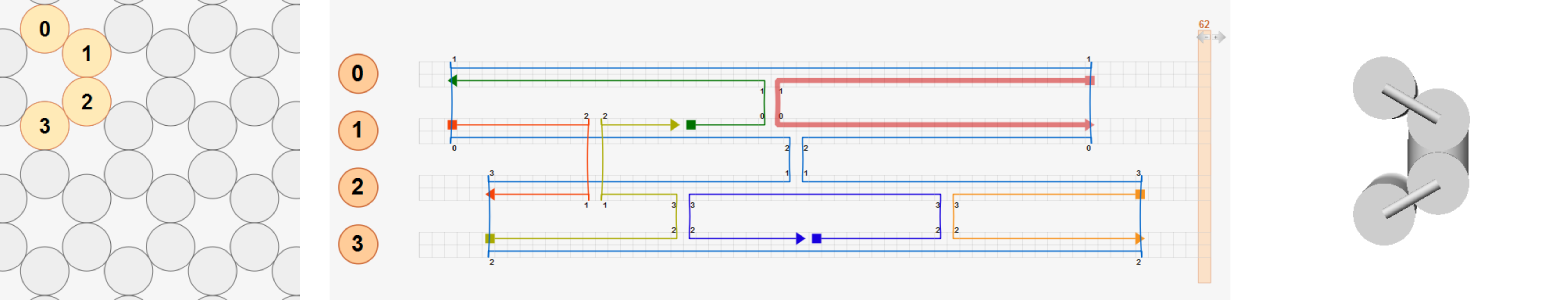
According to positions of the nucleotides in the lattice-free design, CanDo assigns each four-way junction a certain isomeric state. The following figure describes a simple example. The two four-way junctions (designed by Tiamat) on the left and right have the identical nucleotide sequences and secondary structure. The angles between the four arms, nevertheless, are distinct in the two junctions. CanDo correspondingly assigns two different isomeric states to these junctions, as shown beside the Tiamat designs.
A junction stays in the initially assigned isomeric state during the entire analysis process. Therefore, users need to ensure that the angles between junction arms in Tiamat or .cndo design files are close to those in the desired isomeric state.
2. Rotational misalignments between two DNA duplex ends
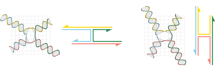
CanDo allows two remote DNA duplex ends to be connected in a Tiamat or .cndo design file. The rotational misalignment angle between these pair of duplex ends gradually reduces to zero when CanDo solves for the equilibrium structure. The mechanical model used by CanDo is not able to recognize misalignment angles greater than or equal to 180°. In the figure below, the rotational misalignment between a pair of duplex ends gradually increases from 0° to 210° in the counter-clockwise direction. The counter-clockwise misalignment angle of 210° will be treated as a clockwise misalignment angle of 150°.

This model property may affect equilibrium structures. The figure below shows two Tiamat designs with the identical secondary structure. Compared to the design on the left, three local components of the design on the right rotate about their axes by 90°, 180°, and 270°, respectively. The two equilibrium structures generated by CanDo are fundamentally different.
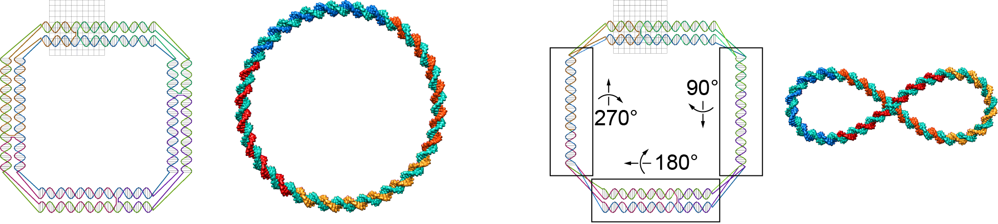
Therefore, users should avoid introducing rotational misalignments that are greater than or equal to 180° between junction ends.